Newer devices
Starburst Turret
How to build things like this
Robot
About Me
More information about the evil robot
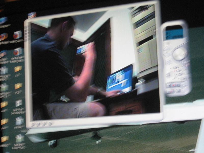
(I like this
picture. It's the digital
camera's view of the screen, while the robot is looking at me taking
the picture.)
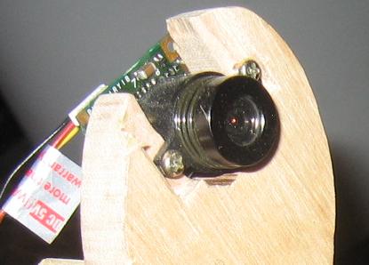
The video system is all from Misumi Electronics. They don't have prices on the site; you have to ask for quotes (I think they don't really intend to sell to hobbyists, but they will sell quantities of 1 if you ask. Allow a few weeks to finalize the order and get it shipped from Taiwan, though. Plus around $20 shipping.) The video camera I used was a CCD camera and was around $40; they have CMOS color cameras for $25. I haven't used the CMOS camera, so I don't know if there's a real difference. The camera outputs a standard video signal, just like a VCR, so you can hook it up to anything that takes a video signal.
I used a video transmitter and receiver from the same company. The pair is around $90, and transmits for a long distance, like a quarter mile. The transmitter takes the TV signal from the camera, and the receiver outputs the signal. I use a video capture card to watch the video on my PC. The transmitter also takes an audio signal, so I put a microphone on the robot too.
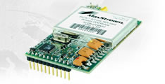
The commands get from the computer to the robot through the Maxstream XCite OEM RF Module. It's $40, so $80 for a pair. You just power them both with 5V, and when you send serial data into one, it comes out the other one. The radios are 2-way (though I only sent data one way). They're really easy to use. The only thing I had to do was use a MAX232 chip to convert computer serial port voltages into standard 5V circuit voltages for the transmitting radio. (There's information about that in any online tutorial about talking to PICs through a serial port. You'll want to read those if you try something like this, as it's really easy to make mistakes and have nothing work. ComTester is a useful program if you're trying to get serial communications to work. The website seems to be down, so here's a link to it on my server: COMtester.exe)
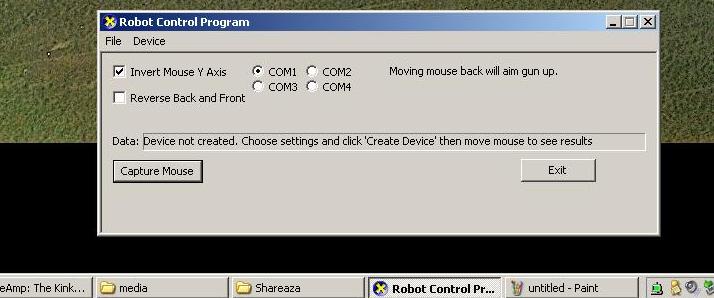
My computer program is just a modification of the DirectX demo from Microsoft that demonstrates how to get mouse input. I basically took it and added code to get both mouse and keyboard input and then send that data through the serial port. That was one of the hardest parts of the project for me since I'd never done Windows programming, but the program was actually not very complex. For aiming, the program just takes the speed of the mouse and matches the speed of the robot's aiming motors to it. (What it sends through the serial port is just a number telling the PIC how many clock cycles to wait between "steps" of the step motor. I tried to have the PIC do as little work as possible-- PC's are faster, and it's easier to modify the PC program than the PIC program.) For movement, the program just sends two-character commands; the PIC program interprets them and does the appropriate thing with the movement motors (i.e. left motor forward, right motor back, etc.) Below is a screenshot. (To control the robot, I open the incoming video from my video capture card while running this robot control program at the same time.)
Aiming Motors
The aiming motors are large step
motors, $49 and $65, from an
Australian company. (I'm sure there are better sources,
though.)
The horizontal motion is done with a turntable. It's a round piece of
wood on a 6-inch "lazy susan" bearing; the bearings are about $6 at McMaster-Carr or
other places.
The horizontal aim motor has a pulley attached to its shaft. A belt
goes
around the pulley, and around the big wood turntable (which has a
groove in it for the belt). The belt is a "round belt" from
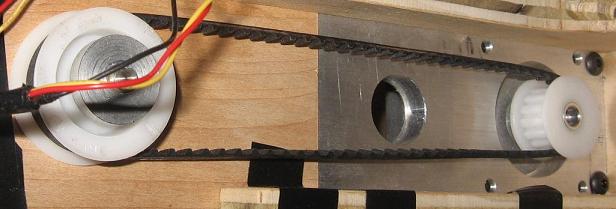
McMaster-Carr, and the pulley is a round belt pulley made to fit it.The vertical aiming is done with an assembly that sits on top of that turntable. A timing belt pulley is attached to the motor; it turns a timing belt that turns another timing belt pulley which is attached to the gun. All of the hardware is from McMaster-Carr. The vertical aiming assembly was built by the Electrical and Computer Engineering Department machine shop at my college. (I had originally wanted to have a cool tank-treaded robot that could climb stairs like an iRobot Packbot, but my independent-study-project budget was only enough to pay for the vertical part of the aiming mechanism. The machine shop foreman still gave me a lot of helpful advice with my mechanical design, though.)
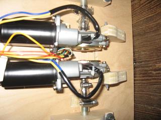
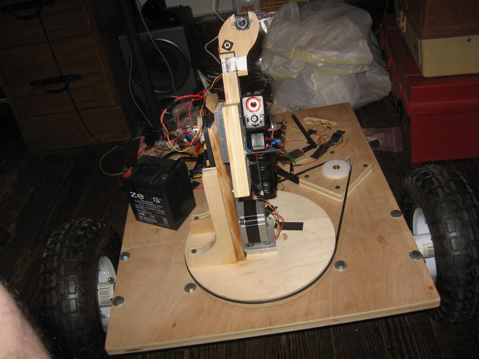
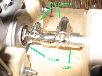
The motors that move the robot around are simpler; each one just drives a wheel directly. They're 12V DC gearmotors designed for car power windows; you can find ones like them for around $20 at various online surplus places or Ebay. I think they work really well for robot motion; they're not too fast or slow and have good torque. The fact that the gearing is integrated with the motor makes things simple and compact. The process of actually mounting them was kind of difficult, though. For each motor, I attached a piece of thick plywood to the robot body and bolted the motor to that, as you can see above.
The wheels I used were $5 each from a hardware store; they're meant for lawn mowers, I think. They're made to fit a 1/4-inch axle. The problem was that they had integrated bearings, so they could initially spin freely on the axle. I needed them to turn with the axle when the motor turned it. So I drilled a hole all the way through the metal part of the wheel and the axle, and put a cotter pin through the hole so that the wheel had to turn when the axle did. The drilling itself was kind of tricky; I had to drill through the bearing, which had ball bearings inside it. Sometimes the ball bearings would just spin against the drill bit rather than being drilled through. It turned out that the best way was to drill a small hole first; it would deform things in the bearing enough that the ball bearings would either be pushed out of the way or stuck in place. Then I could enlarge the hole with a larger drill bit.
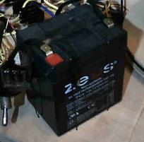
The battery that powers the whole robot is a 12V lead-acid rechargeable battery. It's basically a little version of a car battery. It was $17 at the same surplus place as the movement motors. I charge it with a car battery charger ($20 from a hardware store). The only thing to worry about is that it has a maximum charging current (printed on the battery). The car battery charger I got has a current meter on it, so I used that to make sure that it wasn't giving it too much current. It turned out to be fine with no adjustment; if it had charged too fast, I would have added a small resistor, like 1 or 2 ohms, between the charger and battery to limit the current. (A small resistor would also have let me measure the current if the charger didn't have a current meter. Use a multimeter to measure the voltage across the resistor, and you can calculate the current through it.) The battery worked pretty well; it can easily supply enough current to power the robot (several amps when it's both moving and aiming), and it stores 5 amp-hours; it could theoretically power the robot for over an hour.
The battery, and several other parts, are attached to the robot body with anchor wire, which is thin flexible wire from a hardware store. Other things are attached to the body with cable ties or screws. The body is just a big square of thick plywood.